Chapter 11
State machines can be pictured visually using symbols from the Unified Mod
eling Language (UML), which was introduced briefly at the end of Chapter 3.
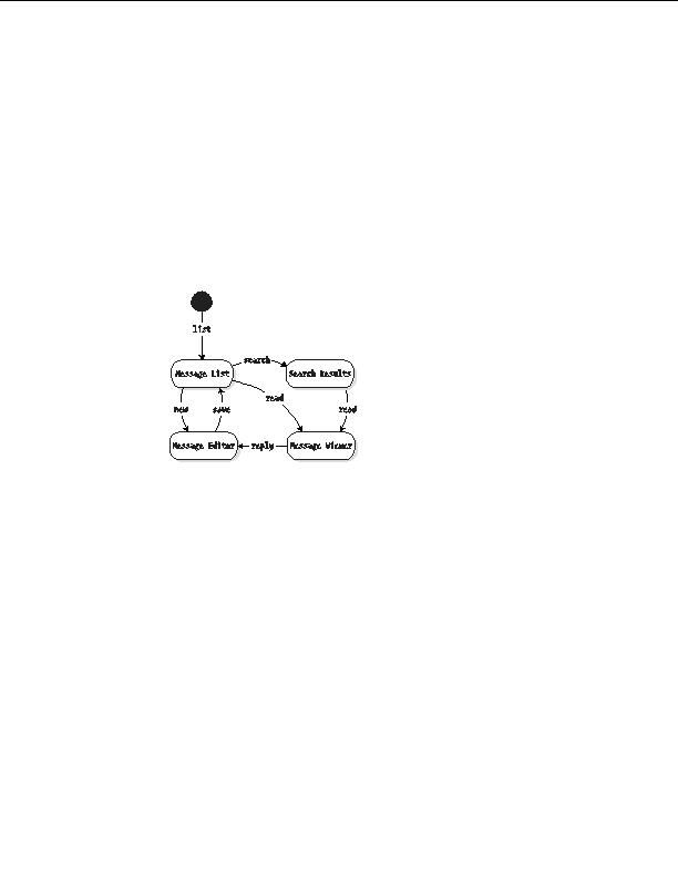
Figure 11 5 shows a state machine for the BBS application. The four boxes rep
resent the four screens of the application. The arrows pointing from one state to
the next are the events. From any given state, there are a fixed number of available
events, or transitions. The diagram begins with an initial state, shown as a filled
circle. The default event list leads from the initial state to the first real state.
This means that when users first arrive at the application, they should be shown a
list of messages.
Figure 11 5. State machine for BBS application
By using a state machine to design your CGIs, you are able to view the appli
cation as a whole. Each event that is accessible from a particular state will generally
show up in the final application as a button or link. With this knowledge, you can
use state transition diagrams to assist you in designing both your user interface
and your program code. Also, the state transition diagram can notify you if you're
missing a button on a particular screen.
The CGI::Application module recognizes that Web applications are best
understood as state machines. As you are about to see, this module provides a
reusable alternative to rolling your own ad hoc flow control from if elsif blocks.
CGI::Application to the Rescue
CGI::Application offers a cleaner solution to this CGI project. Listings 11 1 and 11 2
show the full CGI::Application version browse through it and then I'll walk you
through the code.
258
footer
Our partners:
PHP: Hypertext Preprocessor Best Web Hosting
Java Web Hosting
Inexpensive Web Hosting
Jsp Web Hosting
Cheapest Web Hosting
Jsp Hosting
Cheap Hosting
Visionwebhosting.net Business web hosting division of Web
Design Plus. All rights reserved

